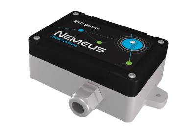
NIS-TR Temperature Sensor (RTD)
Contents
1 General information
2 Mechanics
- Dimensions 60 x 95 x 85mm (109mm including fixing brackets)
- 96mm spacing between brackets
- IP 65
- Solid ABS & PC material
3 RTD Temperature sensor properties
- Handles 100Ω to 1kΩ (at 0°C) Platinum RTDs (PT100 to PT1000)
- 2-wires, 3-wire or 4-wire connection
- 15-Bit ADC Resolution; Nominal Temperature Resolution 0.03125°C (Varies Due to RTD Nonlinearity)
- Total Accuracy Over All Operating Conditions: 0.5°C (0.05% of Full Scale) max
- ±45V Input Protection
- Fault Detection (Open RTD Element, RTD Shorted to Out-of-Range Voltage, or Short Across RTD Element)
- Direct fifth-order linearization for best accuracy
4 Wiring
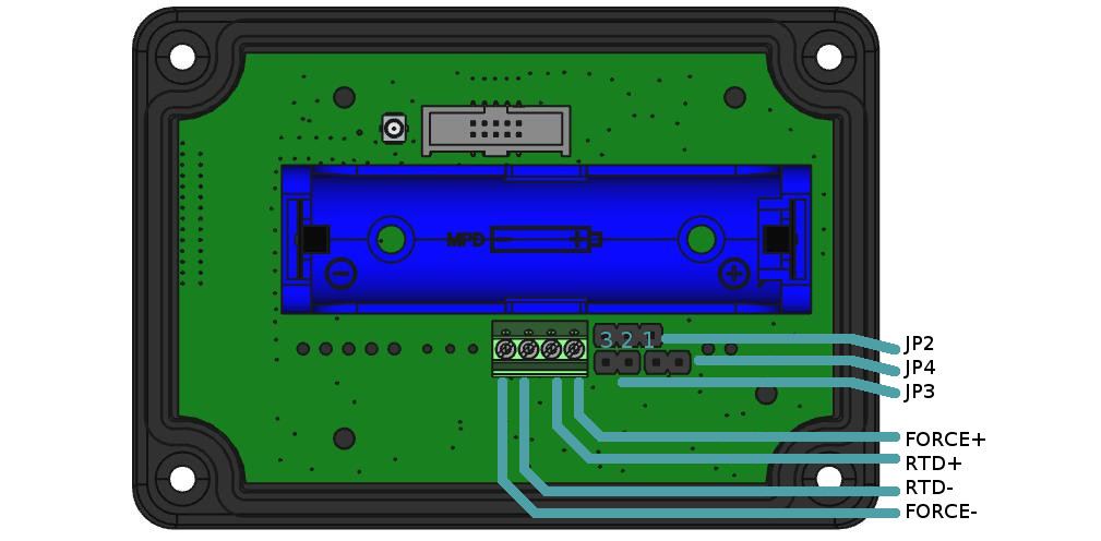
| number of wires | jumpers configuration | Probe connection |
| 4 wires | JP2 jumper on 1-2 | FORCE+ IN+ IN- FORCE- |
| JP3 NC | ||
| JP4 NC | ||
| 3 wires | JP2 jumper on 2-3 | FORCE+ IN+ IN- |
| JP3 NC | ||
| JP4 jumper ON | ||
| 2 wires | JP2 jumper on 1-2 | IN+ IN- |
| JP3 jumper ON | ||
| JP4 jumper ON |
5 Magnetic Switch Protocol description
MSxxx Generic Magnetic Switch Protocol
6 Radio frames description
MSxxx Generic Application Protocol
6.1 Uplink data Frame format
The uplink payload contains multiple fields: <mask>: bit field on 1 byte indicating the presence of other fields. Bit 7 is always to 1 because the mask is never extended on next byte.
bit 0 : indicates the presence of <nb_meas> field.
bit 1 : indicates the presence of <rtd_temp> field.
bit 2 : indicates the presence of <voltage> field.
bit 3 : indicates the presence of <internal_temp> field.
bit 4 : is reserved.
bit 5 : indicates the presence of <cause> field.
When bit 0 is not set, it means that other fields are present only once (nb_meas = 1).
if (mask.bit0 == 1) :
<nb_meas>: 1 byte containing the number of measures which follow.
if (mask.bit1 == 1) :
<rtd_temp>: 2*<nb_meas> bytes containing the temperature values in 0.1 °C. Each temperature value is a signed integer on 16 bits in big endian [-32768..+32767].
if (mask.bit2 == 1) :
<voltage>: 2*<nb_meas> bytes containing the voltage values measured by the sensor in millivolts. Each voltage value is an unsigned integer on 16 bits in big endian.
if (mask.bit3 == 1)
<internal_temp>: 1*<nb_meas> bytes containing the internal temperature values (using MCU internal sensor). Each temperature value is a signed integer on 8 bits in big endian in °C [-128..+127].
if (mask.bit5 == 1) :
   <cause>: 1 byte containing the cause of the uplink frame. It is a bit field:
       Bit 0 indicates a periodic measure
       Bit 1 indicates the high threshold exceeding (temperature > high threshold)
       Bit 2 indicates the high hysteresis exceeding (temperature < high threshold - high hysteresis)
       Bit 3 indicates the low threshold exceeding (temperature < low threshold)
       Bit 4 indicates the low hysteresis exceeding (temperature > low threshold + low hysteresis)
       Bit 5 indicates the measure has been forced manually (with magnetic switch)
   Usually <cause> field is absent when threshold detections are disabled (periodic measures only)
Thus the uplink frame format is <mask><nb_meas><rtd_temp1>...<rtd_tempN><voltage1>...<voltageN><internal_temp1>...<internal_tempN><cause>
Default <mask> value is 0x83 which means that the default frame is <mask><nb_meas><rtd_temp1>...<rtd_tempN>
Some examples (in hexadecimal):
   “820119”: the frame indicates one temperature measurement of +28.1 °C.
   “8302FFCB000C”: the frame indicates two temperature measurements of -5.3 °c and +1.2 °C.
6.2 Downlink Frame format
The sensor configuration contains the following fields:
   <up_frame_mask>: the mask identifying the different fields present in uplink frames (possible values are described in “Uplink data Frame format” section)
   <nb_meas_for_tx>: the number of measures required to trigger a transmission (possible values are [1..8]
   <meas_period>: the period of the measures in <perdiod_unit> seconds(possible values are [600..65535]
   <period_unit>: the unit of <meas_period> in seconds, the resulting period is <meas_perios>*<period_unit> seconds
   <mode>: bit field enabling/disabling the measures (threshold detections and periodic measures)
   <subperiod>: subdivision of period for threshold detection, actual measurement period is (<meas_period>*<period_unit>)/<subperiod> seconds
   <high_threshold>: value of high threshold
   <high_hysteresis>: value of high hysteresis
   <low_threshold>: value of low threshold
   <low_hysteresis>: value of low hysteresis
   <sensor_type>: identifies the type of sensor (PT100/PT1000 and 2/3/4 wires)
It is possible to change the sensor configuration using the Nemeus downlink protocol. The downlink frame must be sent on the MS008 LoRaWAN port (10).
The downlink frame has the following format:
<cmd>: 1 byte containing WRITE_CFG_CMD=0x02
<mask>: bit field on 1 byte indicating the presence of other fields. Most significant bit (bit7) is always to 1 because the mask is never extended on next byte.
Bit0 indicates the presence of <up_frame_mask> field
Bit1 indicates the presence of <nb_meas_for_tx> field
Bit2 indicates the presence of <meas_period> and <period_unit> fields
Bit3 indicates the presence of <mode> and <subperiod> fields
Bit4 indicates the presence of <high_threshold> and <high_hysteresis> fields
Bit5 indicates the presence of <low_threshold> and <low_hysteresis> fields
Bit6 indicates the presence of <sensor_type> field
If (mask.bit0 == 1):
<up_frame_mask>: 1 byte containing the uplink frame mask
If (mask.bit1 == 1):
<nb_meas_for_tx>: 1 byte containing the number of measures required to trigger a transmission
If (mask.bit2 == 1):
   <meas_period>: 2 bytes in little endian (LSB first) containing the period of measures in <period_unit> seconds
   <period_unit>: 1 byte containing the unit of <meas_period> in seconds (default value is 1 second)
If (mask.bit3 == 1):
   <mode>: 1 byte encoded as follows:
       bit0: enable(1)/disable(0) high threshold detection
       bit1: enable(1)/disable(0) high hysteresis detection (when leaving high threshold state)
       bit2: enable(1)/disable(0) low threshold detection
       bit3: enable(1)/disable(0) low hysteresis detection (when leaving low threshold state)
       bit4: enable(1)/disable(0) periodic measurements
       bit5 to bit7: reserved
   <subperiod>: 2 bytes in little endian containing the period subdivision
If (mask.bit4 == 1):
   <high_threshold>: signed integer on 2 bytes in little endian containing the high threshold in 0.1 °C [-2000..+8000]
   <high_hysteresis>: unsigned integer on 1 byte containing the hysteresis when leaving high threshold state in 0.1 °C [0..255]
If (mask.bit5 == 1):
   <low_threshold>: signed integer on 2 bytes in little endian containing the low threshold in 0.1 °C [-2000..+8000]
   <low_hysteresis>: unsigned integer on 1 byte containing the hysteresis when leaving low threshold state in 0.1 °C [0..255]
If (mask.bit6 == 1):
   <sensor_type>: unsigned integer on 1 byte containing the sensor type [11..16]
       11(0x0B): PT100 2 wires
       12(0x0C): PT100 3 wires
       13(0x0D): PT100 4 wires
       14(0x0E): PT1000 2 wires
       15(0x0F): PT1000 3 wires
       16(0x10): PT1000 4 wires
Thus the downlink frame format is <cmd><mask><up_frame_mask><nb_meas_for_tx><meas_period><period_unit><mode><subperiod><high_threshold><high_hysteresis><low_threshold> <low_hysteresis><sensor_type>.
Some examples in hexadecimal:
   “028182”: set the <up_frame_mask> to 0x82 => the next uplink frames will include the <rtd_temp> field only
   “028E0460540110”: set <nb_meas_for_tx> to 4, <meas_period> to 21600*<period_unit> seconds, <period_unit> to 1 second and enable periodic measures only => one measure every 6 hours and one transmission every 4 measures (every day). Each uplink frame will include 4 measures
6.3 Power consumption
Please find below a tool to calculate power consumption vs number of measures and transmissions.

