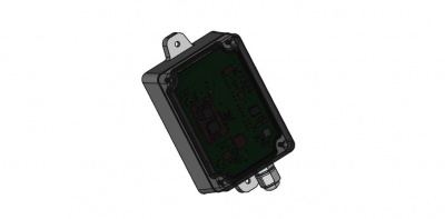
Difference between revisions of "NIS-TR Temperature Sensor (RTD)"
From nemeuswiki
| Line 26: | Line 26: | ||
* Direct fifth-order linearization for best accuracy | * Direct fifth-order linearization for best accuracy | ||
| + | |||
| + | = Wiring = | ||
| + | |||
| + | [[Fichier:MS008 config3.jpeg|picture of sensor pcb and box]] | ||
| + | |||
| + | {| class="wikitable" | ||
| + | |+Probe settings | ||
| + | |- | ||
| + | |number of wires | ||
| + | |jumpers configuration | ||
| + | |Probe connection | ||
| + | |- | ||
| + | |rowspan="3"|4 wires | ||
| + | |JP2 jumper on 1-2 | ||
| + | |rowspan="3"|FORCE+ IN+ IN- FORCE- | ||
| + | |- | ||
| + | |JP3 NC | ||
| + | |- | ||
| + | |JP4 NC | ||
| + | |- | ||
| + | |rowspan="3"|3 wires | ||
| + | |JP2 jumper on 2-3 | ||
| + | |rowspan="3"|FORCE+ IN+ IN- | ||
| + | |- | ||
| + | |JP3 NC | ||
| + | |- | ||
| + | |JP4 jumper ON | ||
| + | |- | ||
| + | |rowspan="3"|2 wires | ||
| + | |JP2 jumper on 1-2 | ||
| + | |rowspan="3"|IN+ IN- | ||
| + | |- | ||
| + | |JP3 jumper ON | ||
| + | |- | ||
| + | |JP4 jumper ON | ||
| + | |} | ||
Revision as of 09:04, 13 July 2017
Contents
1 General information
2 Mechanics
- Dimensions 60 x 95 x 85mm (109mm including fixing brackets)
- 96mm spacing between brackets
- IP 65
- Solid ABS & PC material
3 RTD Temperature sensor properties
- Handles 100Ω to 1kΩ (at 0°C) Platinum RTDs (PT100 to PT1000)
- 2-wires, 3-wire or 4-wire connection
- 15-Bit ADC Resolution; Nominal Temperature Resolution 0.03125°C (Varies Due to RTD Nonlinearity)
- Total Accuracy Over All Operating Conditions: 0.5°C (0.05% of Full Scale) max
- ±45V Input Protection
- Fault Detection (Open RTD Element, RTD Shorted to Out-of-Range Voltage, or Short Across RTD Element)
- Direct fifth-order linearization for best accuracy
4 Wiring
| number of wires | jumpers configuration | Probe connection |
| 4 wires | JP2 jumper on 1-2 | FORCE+ IN+ IN- FORCE- |
| JP3 NC | ||
| JP4 NC | ||
| 3 wires | JP2 jumper on 2-3 | FORCE+ IN+ IN- |
| JP3 NC | ||
| JP4 jumper ON | ||
| 2 wires | JP2 jumper on 1-2 | IN+ IN- |
| JP3 jumper ON | ||
| JP4 jumper ON |
5 Magnetic Switch Protocol description
MSxxx Generic Magnetic Switch Protocol
6 Radio frames description
MSxxx Generic Application Protocol
6.1 Uplink data Frame format
The uplink payload contains multiple fields: <mask>: bit field on 1 byte indicating the presence of other fields. Bit 7 is always to 1 because the mask is never extended on next byte.
Some examples (in hexadecimal): ...
6.2 Downlink Frame format
The sensor configuration contains the following fields:
It is possible to change the sensor configuration using the Nemeus downlink protocol. The downlink frame must be sent on the MS008 ??? LoRaWAN port (8).
The downlink frame has the following format:
<cmd>: 1 byte containing WRITE_CFG_CMD=0x02
Some examples in hexadecimal: ...
6.3 Power consumption
Please find below a tool to calculate power consumption vs number of measures and transmissions.
