Difference between revisions of "NIS-IO Digital Sensor"
From nemeuswiki
(Created page with "== Hardware description == <section begin=Input Electrical Characteristics /> === Input Electrical Characteristics === Two modes selectable with jumper: * Voltage level dete...") |
|||
| Line 1: | Line 1: | ||
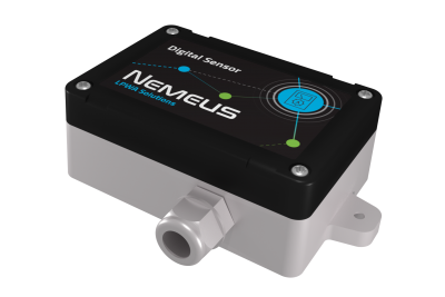
| + | [[File:1 Exp PE Digital Sensor.png|thumb|400px|IO Digital Sensor]] | ||
| + | |||
| + | = General information = | ||
| + | {{:NIS Overview}} | ||
| + | |||
| + | = Mechanics = | ||
| + | * Dimensions 60 x 95 x 85mm (109mm including fixing brackets) | ||
| + | * 96mm spacing between brackets | ||
| + | * IP 65 | ||
| + | * Solid ABS & PC material | ||
| + | |||
| + | = IO Digital sensor properties = | ||
| + | |||
| + | This sensor can monitor up to 4 digital inputs and control 4 digital outputs. | ||
| + | |||
| + | = Wiring = | ||
| + | |||
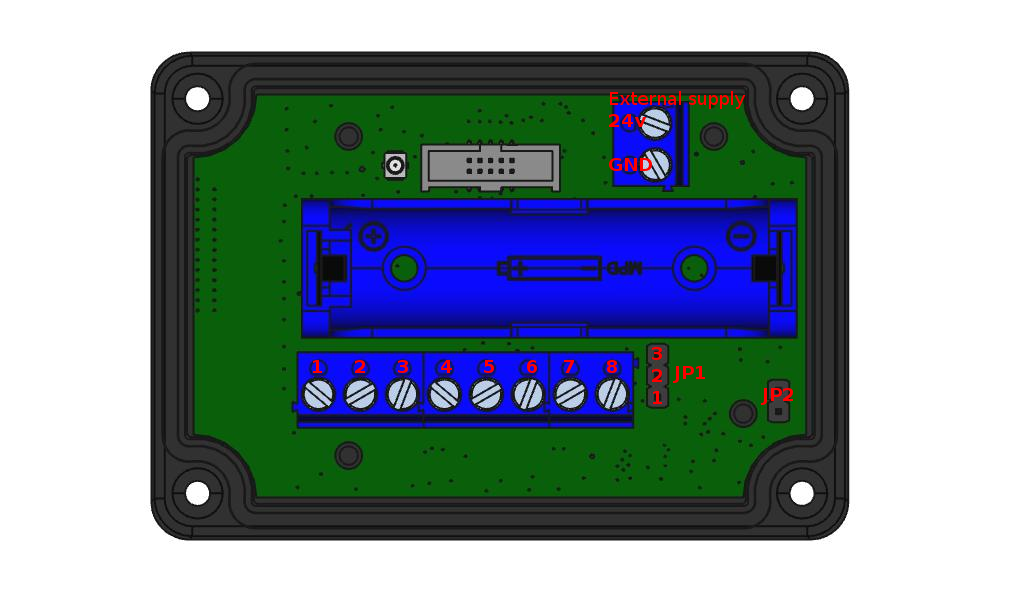
| + | [[File:Full config ids.png|picture of sensor pcb and box]] | ||
| + | |||
| + | |||
| + | {| class="wikitable" | ||
| + | |+Device wiring | ||
| + | |- | ||
| + | |rowspan="2"|IN0 | ||
| + | |1 : IN0+ | ||
| + | |rowspan="8"|JP1 1-2 : No pull for voltage input <br> JP1 2-3 : Pull-up for dry contact | ||
| + | |- | ||
| + | |4 : GND | ||
| + | |- | ||
| + | |rowspan="2"|IN1 | ||
| + | |3 : IN1+ | ||
| + | |- | ||
| + | |4 : GND | ||
| + | |- | ||
| + | |rowspan="2"|IN2 | ||
| + | |5 : IN2+ | ||
| + | |- | ||
| + | |6 : GND | ||
| + | |- | ||
| + | |rowspan="2"|IN3 | ||
| + | |7 : GND | ||
| + | |- | ||
| + | |8 : IN3+ | ||
| + | |} | ||
| + | |||
| + | |||
== Hardware description == | == Hardware description == | ||
<section begin=Input Electrical Characteristics /> | <section begin=Input Electrical Characteristics /> | ||
Revision as of 17:01, 14 December 2017
Contents
1 General information
1.1 Overview
- LoRa™ WAN 1.0.2 EU Class A & C
- Activation by Personalization (ABP)
- Over-The-Air Activation (OTAA)
- SIGFOX™ ready
- Fully certified on major LoraWan & Sigfox networks
- Easy to use and deploy
- 3.6V / 2200mAh Primary battery Li-SOCl2 embedded
- Magnetic switch and LED to ease the installation
- RoHS conform / Pre-Certified ETSI EN 300-220 / RED compliance under certification
1.1.1 RF Performance
- TX Power 14 dBm (25 mW)
- RX Sensitivity -137 dBm
- Approx. 10 km range
- Integrated PCB antenna
1.1.2 Environment
- Operating temperature -40°C to +85°C
- Storage temperature 30°C recommended (to limit battery self-discharge)
- Rel. humidity 0% to 95% (not condensing)
1.1.3 Options
- External antenna
- SDK for your SW development purposes
- 10-30V external power supply
- Compatible with the NEMEUS PicoGateway for private networks
1.2 Installation
By using the internal antenna, the position of the sensor is critical.
Install your product as high as possible, and prefer unobstructed area (concrete and metal are the worst materials).
If you cannot fulfill these conditions, it is still possible to use an optional external antenna.
2 Mechanics
- Dimensions 60 x 95 x 85mm (109mm including fixing brackets)
- 96mm spacing between brackets
- IP 65
- Solid ABS & PC material
3 IO Digital sensor properties
This sensor can monitor up to 4 digital inputs and control 4 digital outputs.
4 Wiring
| IN0 | 1 : IN0+ | JP1 1-2 : No pull for voltage input JP1 2-3 : Pull-up for dry contact |
| 4 : GND | ||
| IN1 | 3 : IN1+ | |
| 4 : GND | ||
| IN2 | 5 : IN2+ | |
| 6 : GND | ||
| IN3 | 7 : GND | |
| 8 : IN3+ |
4.1 Hardware description
<section begin=Input Electrical Characteristics />
4.1.1 Input Electrical Characteristics
Two modes selectable with jumper:
- Voltage level detection, polarity agnostic
- Integrated pull-UP for dry contact input
- Maximum Input Voltage +/-35V
- Detection level +/- 1.8V
- Opto-isolated 3,750 Vrms
<section end=Input Electrical Characteristics />
<section begin=Output Electrical Characteristics />
4.1.2 Output Electrical Characteristics
- ESD Protected
- Thermal shutdown with auto restart
- Short circuit and overload protection
- Overvoltage protection
- Current limitation
- Can drive resistive, inductive and capacitive loads
- Maximum Voltage 42V
- ON resistance 50mΩ
- Nominal load current 3A
<section end=Output Electrical Characteristics />

