Difference between revisions of "MM002 Evaluation Kit (MK002)"
(Created page with "Category:Products '''The MK002 USB key is the evaluation Kit for MM002 modules''' All information can be found from MM002 documentation. 300px...") |
m |
||
| (One intermediate revision by the same user not shown) | |||
| Line 1: | Line 1: | ||
| − | [[Category: | + | [[Category:Modules]] |
'''The MK002 USB key is the evaluation Kit for MM002 modules''' | '''The MK002 USB key is the evaluation Kit for MM002 modules''' | ||
| Line 12: | Line 12: | ||
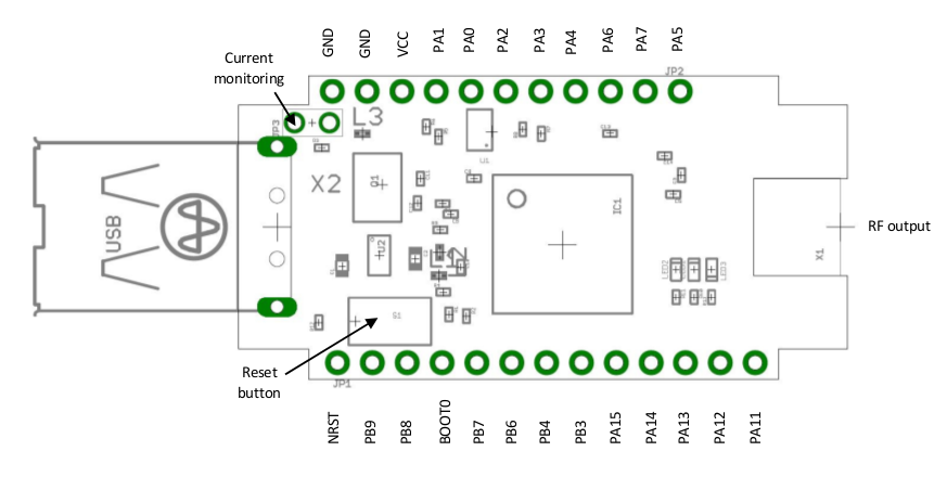
== Pinning == | == Pinning == | ||
| − | [[File:Mk002-pinning.png | + | [[File:Mk002-pinning.png]] |
== Current monitoring == | == Current monitoring == | ||
| + | <br> | ||
| + | |||
| + | {| | ||
| + | |- | ||
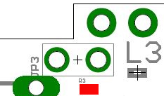
| + | | [[File:Mk002-pinning_r3.png]] || || To measure current consumption of MM002 module, remove 0ohm resistor R3 (in red) and place ampere meter in serial way on connector JP3. | ||
| + | |} | ||
| − | |||
| − | |||
== External power supply settings == | == External power supply settings == | ||
| Line 34: | Line 38: | ||
== UART Connection == | == UART Connection == | ||
| − | To use UART2 connexion (pins PA2 and PA3) on another test board, it is mandatory that the USB key | + | To use UART2 connexion (pins PA2 Tx and PA3 Rx) on another test board, it is mandatory that the USB key |
is unplugged from PC. This will then remove power supply from IC1 and avoid any conflict on UART2 | is unplugged from PC. This will then remove power supply from IC1 and avoid any conflict on UART2 | ||
pins. | pins. | ||
Latest revision as of 09:40, 11 April 2017
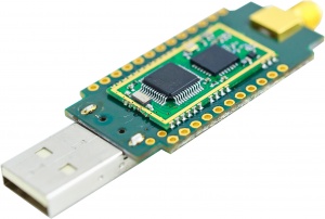
The MK002 USB key is the evaluation Kit for MM002 modules
All information can be found from MM002 documentation.
This page includes specific documentation, examples and resources to use the MK002
Contents
1 Pinning
2 Current monitoring
 |
To measure current consumption of MM002 module, remove 0ohm resistor R3 (in red) and place ampere meter in serial way on connector JP3. |
3 External power supply settings
It is also possible to supply the MM002 module by other voltage source than USB. For that, remove R3, and connect supply between GND and VCC pins.
Please refer to MM002 supply recommendations in MM002 datasheet.
4 Reset button S1
A reset button is mounted. Press the button to reset the MM002 module.
5 JP1 and JP2 connectors
These connectors are not provided. The pitch of each connector is 2.54mm.
6 UART Connection
To use UART2 connexion (pins PA2 Tx and PA3 Rx) on another test board, it is mandatory that the USB key is unplugged from PC. This will then remove power supply from IC1 and avoid any conflict on UART2 pins.
This operation will then require to supply externally the module with the procedure described above in paragraph “external power supply settings”. For complete information on pins PA2 and PA3, please refer to latest module’s datasheet on nemeus website.

