Difference between revisions of "NIS-UL UltraSonic Sensor"
m |
|||
| Line 81: | Line 81: | ||
== Status Frame format == | == Status Frame format == | ||
== Configuration Frame format == | == Configuration Frame format == | ||
| + | == Power consumption == | ||
| + | |||
| + | |||
| + | Please find below a tool to calculate power consumption vs number of measures and transmissions. | ||
| + | |||
| + | |||
| + | {{#widget:Iframe|param=https://jscalc.io/calc/7Z9r3VnBuApcPSzj|width=100%|height=800}} | ||
Revision as of 15:56, 20 June 2017
Contents
1 General information
2 Mechanics
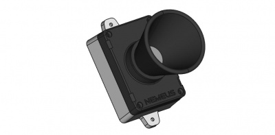
- Dimensions 60 x 95 x 85mm (109mm including fixing brackets)
- 96mm spacing between brackets
- IP 65
- Solid ABS & PC material
3 WARNING
This sensor is not designed for critical purposes. It should never be used in an application where a malfunction of the device could cause personal injury. Due to ultrasonic physics, we can not guarantee 100% reliability at close distances.
4 Ultrasonic sensor properties
Default configuration allows target detection until 6 meters.
Objects from 0cm to 20cm range as 20cm or closer.
The acoustic detection pattern has an angle of 7°. The geometry of the detection pattern depends mainly on the size, orientation, and acoustic properties of the target, but also on the atmospheric pressure, temperature and humidity.
Each sensor is factory calibrated to unify results between sensors.
5 Magnetic Switch Protocol description
MSxxx Generic Magnetic Switch Protocol
6 Radio frames description
MSxxx Generic Application Protocol
6.1 Uplink data Frame format
The uplink payload contains multiple fields: <mask>: bit field on 1 byte indicating the presence of other fields. Bit 7 is always to 1 because the mask is never extended on next byte. Least significant bit (bit 0) indicates the presence of <usonic_dist> field, bit 2 indicates the presence of <temp>.
if (mask.bit0 == 1) :
- <nb_meas>: 1 byte containing the number of distance measurements which follows.
- <usonic_dist>: 2 bytes containing the distance measured by the ultrasonic sensor in centimeters (1 to 600 cm).
if (mask.bit2 == 1) :
- <temp>: 1 byte containing the signed integer of the temperature
Thus the uplink frame format is <mask><nb_meas><usonic_dist><temp>.
Some examples (in hexadecimal):
- “8502009700981f”: the frame indicates two measurements of 151cm and 152cm followed by a temperature of 31°C.
- “810100a0”: the frame indicates a single measurement of 160cm without temperature.
- “841e”: the frame indicates a temperature of 30°C.
- “fd02009c009c1cxxxxxxxxxxxx”: the frame indicates two measurements of 156cm and 156cm with a temperature of 28°C followed by private data.
6.2 Downlink Frame format
The sensor configuration contains the following fields:
- <up_frame_mask>: the mask identifying the different fields present in uplink frames (possible values are described in “Uplink data Frame format” section)
- <meas_period>: the period of the measures in seconds (possible values are [600..65535], default value is 14400 seconds => one measure every 4 hours)
- <nb_meas_for_tx>: the number of measures required to trigger a transmission (possible values are [1..8], default values is 6 => 6 measures are sent in one frame every day)
It is possible to change the sensor configuration using the Nemeus downlink protocol. The downlink frame must be sent on the MS006 LoRaWAN port (8).
The downlink frame has the following format:
<cmd>: 1 byte containing WRITE_CFG_CMD=0x02
<mask>: bit field on 1 byte indicating the presence of other fields. Most significant bit (bit7) is always to 1 because the mask is never extended on next byte. Least significant bit (bit0) indicates the presence of <up_frame_mask> field, bit1 indicates the presence of <nb_meas_for_tx> and bit2 indicates the presence of <meas_period>
If (mask.bit0 == 1):
- <up_frame_mask>: 1 byte containing the uplink frame mask
If (mask.bit1 == 1):
- <nb_meas_for_tx>: 1 byte containing the number of measures required to trigger a transmission
If (mask.bit2 == 1):
- <meas_period>: 2 bytes in little endian (LSB first) containing the period of measures in seconds
Thus the downlink frame format is <cmd><mask><up_frame_mask><nb_meas_for_tx><meas_period>.
Some examples in hexadecimal:
- “028181”: set the <up_frame_mask> to 0x81 => the next uplink frames will include the <usonic_dist> field only (no <temp> field)
- “0286046054”: set <nb_meas_for_tx> to 4 and <meas_period> to 21600 seconds => one measure every 6 hours and one transmission every 4 measures (every day). Each uplink frame will include 4 measures
6.3 Status Frame format
6.4 Configuration Frame format
6.5 Power consumption
Please find below a tool to calculate power consumption vs number of measures and transmissions.
